
Intended application
The system for checking alignment of chord coupling flanges is designed to provide automatic testing and registering misalignment magnitudes for chord coupling flanges and distance between outer flange faces of the gear case and the tractive motor of electric trains during assembly after repair and in service.
The system is to operate within heated indoor spaces with the following environmental conditions:
- ambient temperature, С…..…........................….…………...from 5° to 40°;
- relative humidity, %……….............................................…..........65±15;
- pressure, kPa..….…………………………………………...…......... 100±10;
Measured parameters
- Coupling flange misalignment
- Distance between outer flange faces
System components
The system consists of electronic snap gage for measuring misalignment and distance between outer flange faces (hereafter referred to as “gage”) and system software (hereafter referred to as SW), which provides transfer of inspection data to a computer (not included in the scope of supply) and its storage for an inspection results database.
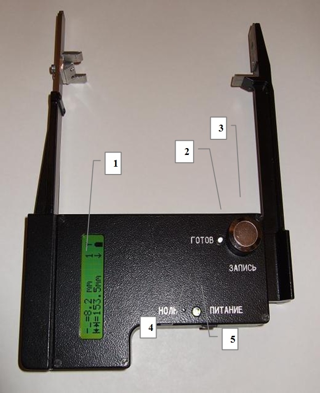 |
Gage display layout |
The gage measures and writes data to memory concerning misalignment magnitudes for chord coupling flanges and distance between outer flange faces of the gear case and the tractive motor. All operational modes of the gage are controlled by a microcontroller. The data memory contains values of the current measurements and the value indicated by the counter of measurements.
As shown in the figure, on the front panel of the gage there are:
- a liquid crystal display ( LCD) 1
- LED indicator “Ready” 2
- RECORD button 3
- ZERO button 4
- LED indicator “Power” 5
 |
LC-display |
Symbols on the LCD indicate:
- misalignment 1;
- distance between outer flange faces 2;
- counter of measurements 3;
- arrow 4 – the arrow indicator is used for facilitating level positioning and shows the direction of rotation of the gage;
- antenna 5 – indicates possibility of wireless connection with a computer;
- battery charge 6.
Technical characteristics
Measurement range:
- coupling flange misalignment, mm………….………..……..from – 8 to +8;
- distance between outer flange faces, mm………….....…from 155 to 190;
Maximum permissible measuring error (at confidence level 0.95), not more than:
- coupling flange misalignment, mm …………………………………...…....0.2;
- distance between outer flange faces, mm ………………...…….............0.5;
The system charger requires power supply from AC mains, voltage (220+22 / -33) V and frequency 50±1 Hz.
Weight max 1kg.
Overall dimensions (WxHxD) 181х247,5х40 mm.
CNT Ltd.
- Manufactures and performs testing of the system for checking alignment of chord coupling flanges
- Provides training for maintenance and operating personnel
- Performs warranty service
- Offers post-warranty service under additional agreements
- Performs adjustments of the equipment to operational conditions